3 · The Complete board
What makes the Complete special
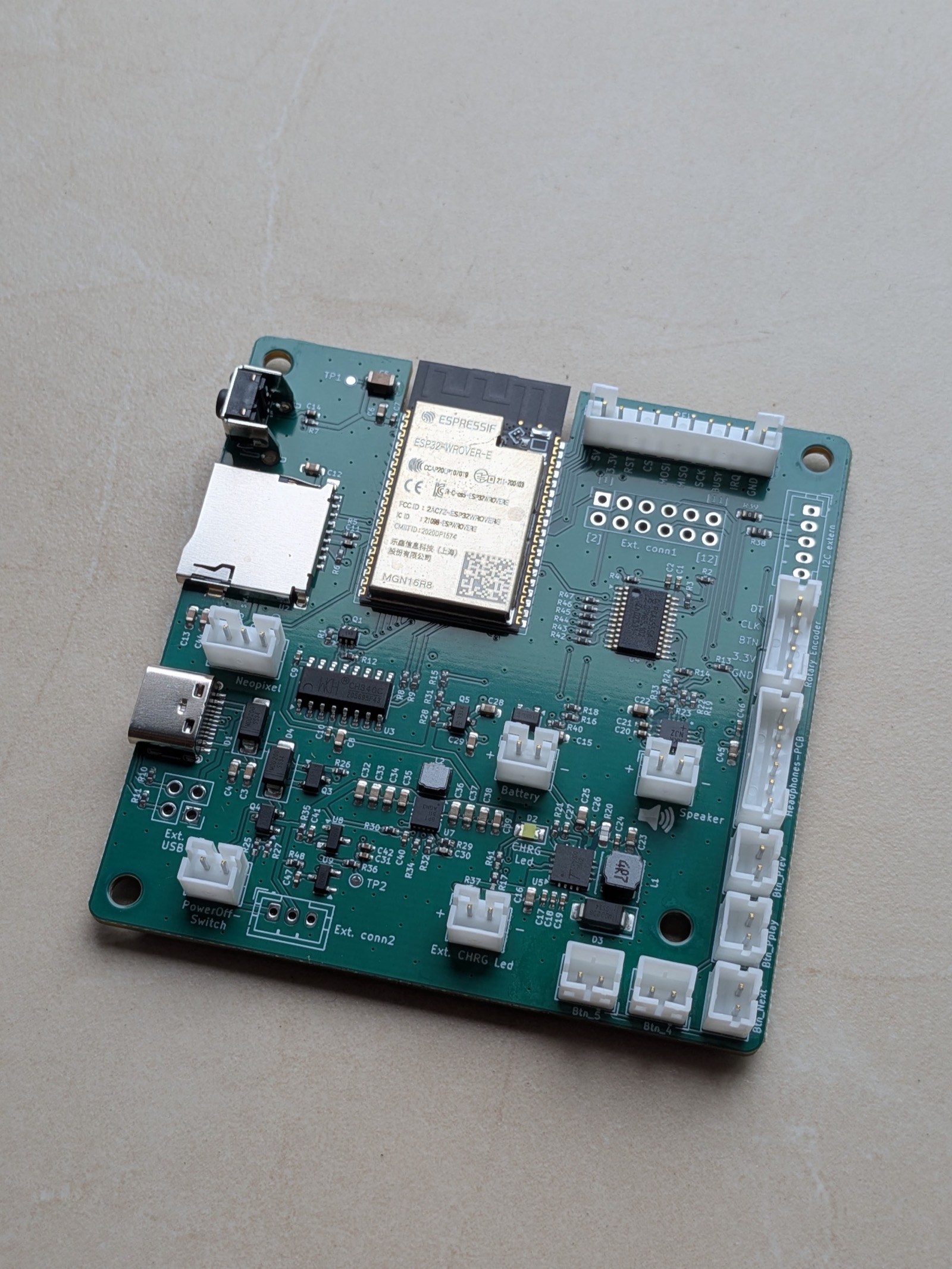
The Complete is the current ESPuino board and the point of reference for this handbook. Its main advantage can be summed up in one word: integration. Where earlier versions still required several modules to be plugged together and wired by hand, the Complete puts almost everything on a single board – ESP32-WROVER, amplifier, charge controller, voltage monitoring, the port expander for extra connections, and the SD card slot. Functionally, it offers essentially the same as the earlier mini4L, but it's cheaper and considerably faster to assemble. Only the headphone board remains a separate, optional add-on.
In practice, that means: you get the board fully populated. SMD soldering – the fine soldering of tiny components – is already done at the factory. What's left to do is soldering a few wires and connectors, which is covered in chapter 5.
Technical specifications
Before we go into detail, the facts at a glance:
| Property | Value |
|---|---|
| Dimensions | 72.2 × 70.6 mm, four mounting holes (⌀ 3.2 mm) |
| Construction | four-layer board, fully SMD-populated |
| Controller | ESP32-WROVER, 16 MB flash, 8 MB PSRAM |
| Power supply | buck/boost switching regulator (TPS63000), constant 3.3 V |
| Inputs | USB-C and/or battery (LiPo or LFP), both reverse-polarity protected |
| Charge controller | fixed max. 1 A charge current, on-board status LED |
| Amplifier | MAX98357A, one speaker output (both channels summed), ~1 W into 4 Ω |
| Audio storage | microSD (SD-MMC, 1-bit), FAT32 |
| Expansion | PCA9555 port expander for additional inputs/outputs |
| Connectors | JST-PH connectors for the RFID reader, speaker, rotary encoder, Neopixels, up to 5 buttons, headphone board, charge LED, power-off switch, and battery; plus USB-C and the expansion connector Ext.Conn1. The I²C connector is left unpopulated from the factory (details). |
Everything else – which wire goes where, what each solder bridge does – is covered in the following sections, including the pinout reference.
The power supply
ESPuino is meant to run from quite different sources – a USB power supply, a LiPo battery, or a LiFePO4 (LFP) battery. And regardless of which one is currently connected and how full the battery is: a stable 3.3 volts must come out the other end for the ESP32.
That used to be exactly the sore point. The mini4L powered the controller through a so-called linear regulator (LDO). Such a regulator "burns off" the excess voltage, but needs a bit of headroom itself: when the battery was nearly empty and delivered only about 3.3 V, only around 3.1 V made it through – already too little for the ESP32, strictly speaking (in practice it usually still worked, but that's not exactly clean design). This gets especially delicate with LFP batteries, which only supply about 3.2–3.3 V to begin with; there, the regulator had to be bypassed outright.
The Complete solves this fundamentally with a buck/boost switching regulator. It can step a voltage that's too high down and step one that's too low up, delivering a constant 3.3 V regardless of source and charge level. On top of that comes an undervoltage cutoff that protects the device before the battery is discharged too deeply. Even so, it should be said up front that this protection never replaces the cutoff function of a BMS, which must be built into the battery pack you use.
Both inputs – USB-C and battery – are also protected against reverse polarity. The built-in charge controller charges the battery at a fixed maximum of 1 A. So that this charge current doesn't overwhelm the battery (rule of thumb: no more than half the capacity per hour, "0.5 C"), the battery should have at least 2000 mAh. The undervoltage cutoff kicks in at different thresholds depending on battery type: around 2.75 V for LFP, around 3.15 V for LiPo. These values deliberately sit with some margin above the absolute discharge limit – that's easier on the battery and prevents brief current spikes (loud audio, for instance) from shutting the device down right away.
Charging & the charge LED
A small status LED on the board shows you the charge state directly:
| LED | Meaning |
|---|---|
| Fast blinking | USB connected, but no battery detected |
| Steady on | USB and battery connected – the battery is charging |
| Off | Battery full (with USB + battery) or running on battery alone |
If you'd like to bring this indicator out to the enclosure, there's a dedicated 2-pin connector for an external charge LED. The necessary series resistor is already on the board, so you can connect the LED directly – just watch the printed polarity.
Worth understanding: while charging, the measured battery voltage isn't meaningful, because the charging process artificially raises it. A reliable charge-level display therefore only exists when running purely on battery (more on that in chapter 4).
Switching on and off
Normally, the button inside the rotary encoder "switches" ESPuino on and off – in reality, it enters the power-saving deep sleep and wakes up immediately on a button press (see the glossary and chapter 9). For most people, that's entirely sufficient.
If you want to lower the idle current even further, you can add a true power switch. The Complete has a dedicated 2-pin power-off connector for this: a switch connected there shuts down the central 3.3 V supply by disabling the output side of the switching regulator – the ESP32 is then genuinely off, not just asleep. Charging over USB keeps working even while the switch is set to "off".
Power-off switch: the drawbacks
- Startup afterwards takes a bit longer (a full cold boot instead of waking from deep sleep).
- A hard power-off switch cannot be combined with the PN5180's LPCD wake-up – the two are mutually exclusive.
Power consumption & power supply
In operation, an ESPuino draws roughly 140 to 350 mA, depending on volume and how bright the Neopixels shine. Add charging on top, and up to 1 A more comes on. So your power supply never runs short – loud playback and charging at the same time – you should use a USB power supply rated for at least 1.5 A.
The amplifier and sound
Sound comes from a MAX98357A, a small class-D amplifier with a built-in digital-to-analog converter. At 3.3 V it delivers roughly 1 watt into a 4-ohm speaker – plenty for a compact audio box at room volume. Small full-range speakers such as the Visaton FR 7 (4 Ω) have proven reliable.
One difference from the mini4L: the Complete has only one amplifier, and therefore one speaker output. "Mono" in the sense of one channel being dropped isn't quite accurate here – the output carries both stereo channels mixed together (the sum of left and right), so nothing is lost. It's a single-channel output – exactly right for a compact audio box. At the headphone output (via the separate headphone board), you do get stereo.
The sound doesn't have to run through the built-in amplifier at all: ESPuino also supports Bluetooth – as a source, to send audio to a Bluetooth speaker or headphones, and as a sink, where ESPuino itself becomes the speaker and you stream to it from, say, your phone. Both modes, and what to watch out for, are covered in chapter 9.
You set the base gain with a solder bridge:
| Solder bridge | Base gain |
|---|---|
| JP2 – set at the factory | +3 dB |
| no bridge | +9 dB |
| JP3 | +15 dB |
Never JP2 and JP3 at the same time
The two bridges are mutually exclusive: only one of the two may ever be set – or neither, in which case it stays at +9 dB.
The factory setting JP2 (+3 dB) tends to be loud enough for an audio box and has a pleasant side effect: at the lower base gain, the software's 21 volume steps sit closer together, so you can fine-tune the volume more precisely. Details on these solder bridges are covered under the solder bridges in chapter 5.
Versions & scope of delivery
The current revision of the Complete is 5.1. It combines both battery variants on a single board – whether LFP or LiPo is set via the solder bridges JP5/JP6 (see chapter 5). The reset button has been populated at the factory since 09/2026.
Only a handful of the earlier boards (rev. 5.0/5.0.1) are in circulation; if you happen to own one, the small differences are noted under the solder bridges in chapter 5.
When ordering, you can choose between three variants – which one suits you depends on how much you want to contribute yourself (details and prices are in the price list #3344, German-language forum):
- Board only – the fully populated Complete on its own, with no further accessories.
- Set 1 – the board together with the necessary connecting wires.
- Set 2 – like Set 1, plus the headphone board.
Specify the battery type when ordering
When ordering, you need to specify whether you want the LiPo or the LFP version. The matching battery type is pre-configured at the factory via the solder bridges on the board – so there's nothing for you to set yourself. If you decide to switch to the other battery type later, that can still be changed afterwards by moving one or two solder bridges (more on that under the solder bridges in chapter 5).
Connectors, controls, pinout
The following pinout reference shows which function sits on which connector – when wiring things up, this is the place to check when in doubt.
Pinout reference
From settings-complete.h. Important: values ≥ 100 are port-expander channels (PCA9555,
channel = value − 100), not direct ESP32 GPIOs; 99 = unused/dummy.
The difference matters in practice: a port-expander channel can't be used as universally as a real GPIO. It's essentially good for reacting to a button (input) or switching something (output) – and even that has to be programmed for your own extensions. More on the port expander in chapter 12.
| Function | Signal | Pin |
|---|---|---|
| Audio (I²S) | DOUT / BCLK / LRC | GPIO 25 / 27 / 26 |
| RFID (SPI) | CS / SCK / MOSI / MISO | GPIO 21 / 18 / 23 / 19 |
| RFID (PN5180 only) | RST / BUSY / IRQ | GPIO 22 / 33 / 32 |
| SD card | SD-MMC 1-bit: CLK / CMD / D0 | GPIO 14 / 15 / 2 |
| Rotary encoder | CLK / DT | GPIO 34 / 39 |
| Rotary encoder | button | PE 105 |
| Buttons | Previous / Pause-Play / Next | PE 100 / 101 / 102 |
| Buttons | Button 4 / Button 5 | PE 103 / 104 |
| Neopixel | LED signal | GPIO 12 |
| Power | peripheral cutoff (POWER) |
PE 114 |
| Power | amplifier (GPIO_PA_EN) |
PE 113 |
| Battery | voltage measurement (ADC) | GPIO 35 |
| Headphones | jack detection (HP_DETECT) |
PE 108 |
| Wakeup / PE interrupt | wake from deep sleep | GPIO 36 |
| IR (optional) | IR receiver | GPIO 5 |
Free GPIOs
On the expansion connector Ext.Conn1, the still free GPIO 0, 5, and 32 are available. Two things worth knowing: GPIO 0 is needed by the ESP32 internally (boot mode) and should only be used for something else in an emergency. GPIO 32 is the PN5180's IRQ line, and is therefore only free as long as you're not using LPCD – in LPCD mode (JP1/JP8), the reader occupies it. GPIO 5, finally, is the input for the optional IR receiver.
The connectors at a glance
Almost everything connects via small JST-PH connectors – each has its own pin count, so they're hard to mix up. This overview shows what goes where:
| Connector | Plug | For |
|---|---|---|
| RFID reader | 10-pin | RC522 or PN5180 (pinout below) |
| Speaker | 2-pin | one mono speaker |
| Rotary encoder | 5-pin | volume + button (on/off) |
| Neopixel | 3-pin | status and progress LEDs |
| Buttons (up to 5) | 2-pin each | Previous, Play/Pause, Next, Button 4/5 |
| Headphone board | 6-pin | optional headphone output |
| External charge LED | 2-pin | optional charge indicator on the enclosure |
| Power-off switch | 2-pin | optional true power switch |
| Battery | 2-pin | LiPo or LFP with BMS |
Never rely on wire colors
Connector pinouts are defined by the labels printed on the board, not by the color of the wires on a finished cable. Before plugging anything in, always check signal by signal against the board's printed labels.
The exact pinout of the RFID connector – 10-pin, with the differences between PN5180 and RC522 – is documented right where you need it: in chapter 5 → RFID connector pinout.
Choosing the components
Some of the parts depend on your own preferences. Here are the decisions ahead of you:
- RFID reader: you can choose between the RC522 (affordable, plenty for most people) and the PN5180 (more sensitive, longer range, and a requirement for the optional LPCD wake-up). Thanks to auto-detection (see below), you don't commit to one via the firmware.
- microSD card: an ordinary microSD card, formatted as FAT32. Cards of 64 GB and above usually come formatted as exFAT from the factory and need to be reformatted first (see note). Very large or very cheap cards also don't always run reliably. If you run into trouble, try a different (smaller) card.
- Battery: optional – ESPuino also runs happily off a USB power supply permanently. For mobile use, the choice between LFP and LiPo is important enough to get its own chapter: see chapter 4 · The battery.
- Speaker: to taste and to fit the enclosure size; a 4-ohm full-range driver like the Visaton FR 7 fits well. The amplifier delivers at most 1 W – an oversized speaker won't gain you anything here.
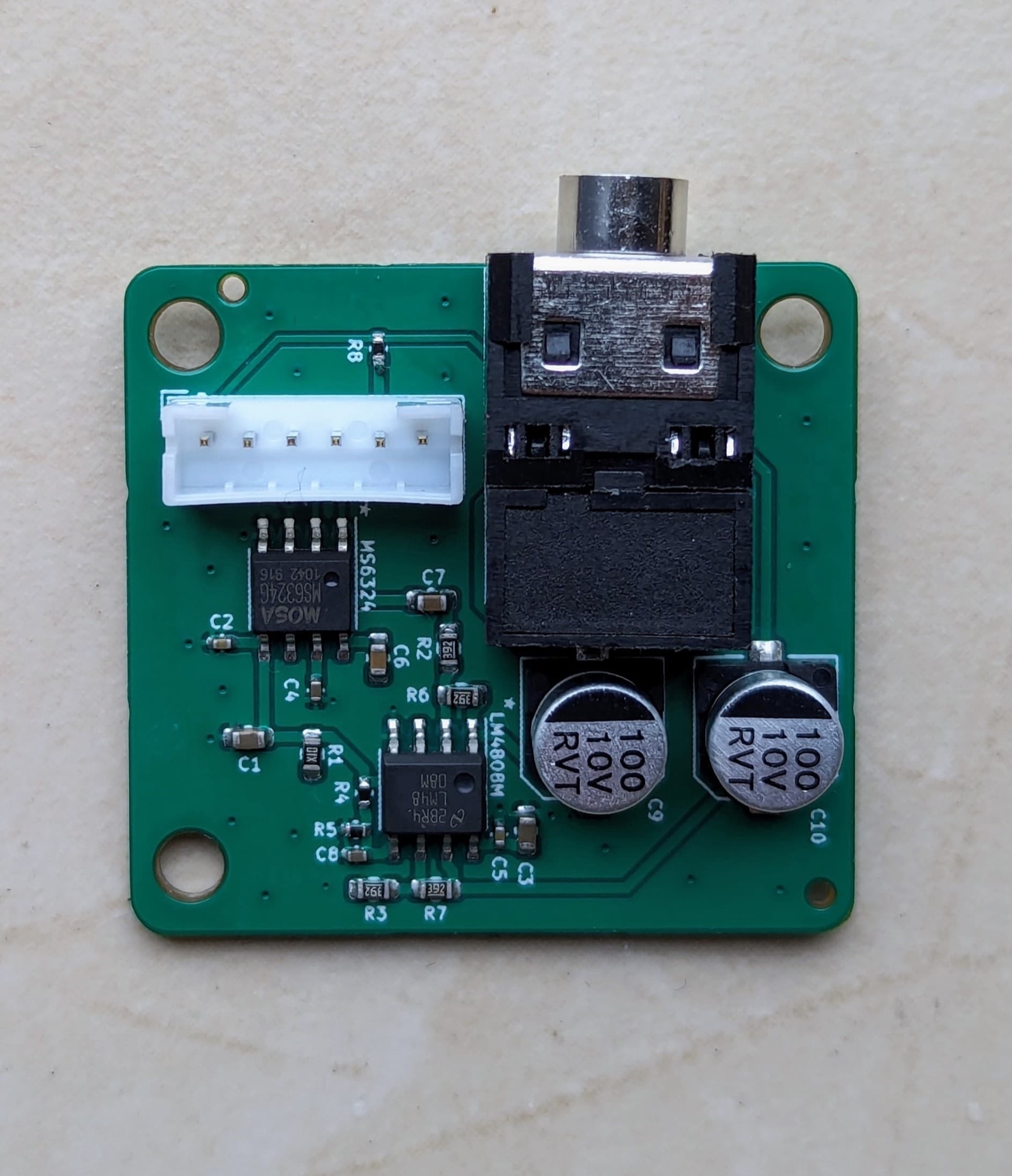
- Headphones: optional via the separate headphone board (based on the MS6324 chip, forum #1099, German-language).
The RFID reader type is no longer a firmware question
You used to have to pick the matching firmware variant for RC522 or PN5180 when flashing. Since May 2026, ESPuino detects the reader automatically at runtime. Choosing the reader is therefore purely a hardware decision you no longer need to worry about when updating the firmware.
Format large cards as FAT32
Cards of 64 GB and above (SDXC) come formatted as exFAT from the factory. Windows doesn't offer FAT32 for cards that large in its standard dialog – a tool like "FAT32 Format" (guiformat) helps here. The official SD Card Formatter is great for cleanly resetting a card, but it formats large cards as exFAT per the SD standard – for FAT32 you'll additionally need the tool mentioned above.
Limits of the board
So you know what the Complete deliberately cannot do:
- Only one amplifier – no true stereo operation with two independently driven speakers.
- No 5 V logic – internally, everything runs at 3.3 V.
- No coulomb counter – the charge level is estimated from battery voltage, not tracked exactly. Especially with LFP, the voltage stays very flat over much of the discharge curve, so the display is correspondingly coarse (more on that in chapter 4).
Schematics, 3D model & documents
If you want to dig deeper or design an enclosure, the Complete thread (#3817) (German-language forum) has the full documentation – schematics (rev 5.0.1 and rev 5.1 as PDF) and a 3D model of the board (STEP file). The mounting holes sit in the four corners (⌀ 3.2 mm); for exact spacing, the 3D model is your best source.
For the advanced: additional connectors
Ext.Conn1, Ext.Conn2, Ext.USB, and the port expander
You don't need these connectors for a normal build – they're meant for special cases and some are left unpopulated at the factory (populated on request).
- Ext.Conn1 brings out additional signals: switched 3.3 V (active only during operation, off during deep sleep), permanent 3.3 V, battery +, the still-free GPIO 0, 5, and 32 (with the caveats from the "Free GPIOs" note above), and the port-expander channels PE109/PE112.
- Ext.Conn2 provides GND and two voltages: OOut (~4.6 V on USB, otherwise battery voltage; USB takes priority) and Vin (same as OOut, but can be switched off by the power-off switch).
- Ext.USB is an alternative 5 V input (VUSB, GND, CC1, CC2); the required 5.1 kΩ resistors are already populated. Caution: this input is not protected against reverse polarity – for experienced users only.
- The PCA9555 port expander provides additional inputs/outputs; internally it handles, among other things, the buttons and a few control lines, and is also covered in chapter 12.
Ordering & accessories
You can get the Complete and optional accessories – such as the headphone board or the rotary encoder kit – from the developer. What's available and what it costs is listed in the forum price list (#3344) (German-language).